Ever wondered why the same roundness tolerance measurement yields different results when measured by American and European suppliers? This blog post delves into the hidden differences between ASME and ISO standards, providing insights and a quick reference guide to ensure accurate and consistent measurements across both systems.
The ASME Approach: Hidden Defaults
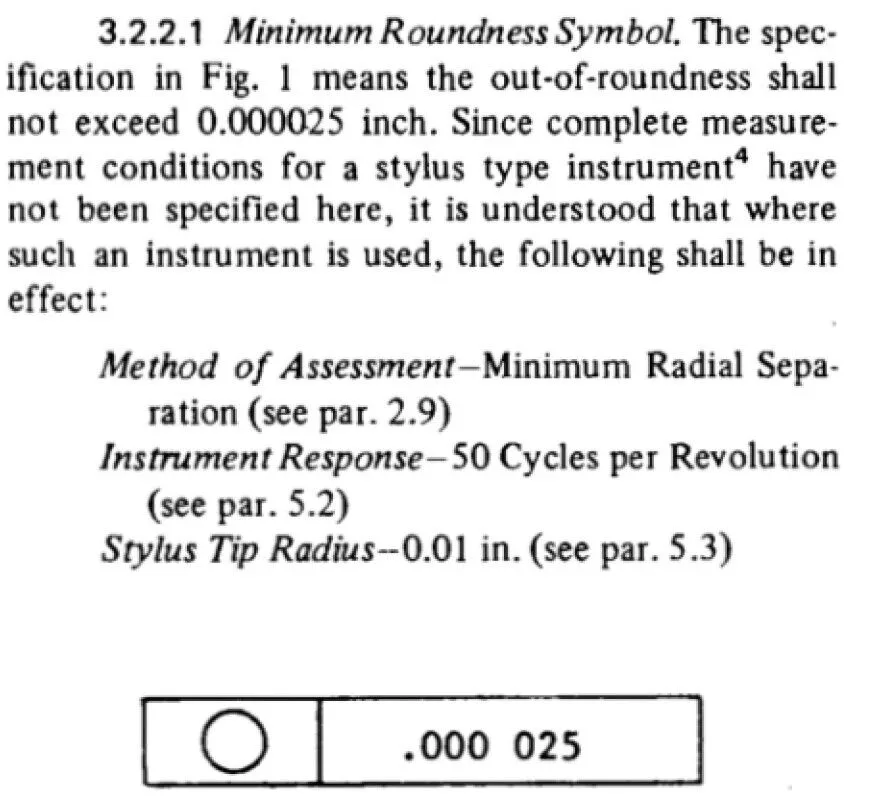
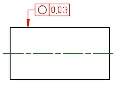
Under the ASME Y14.5 system, roundness tolerance annotations are deceptively simple. A roundness symbol followed by a numerical value might seem straightforward, but beneath this simplicity lies a set of unspoken rules defined by ANSI B89.3.1:
- Evaluation Method: Minimum Radial Separation (MRS) is the default.
- Filter: A 50 UPR (Undulations Per Revolution) filter is used.
- Probe Tip: The default probe tip radius is 0.25 mm.
These hidden defaults mean that all measurements are conducted under a standardized set of conditions, ensuring consistency within the ASME framework. However, this can lead to confusion and discrepancies when compared to ISO standards.
ISO Standards: Transparency and Precision
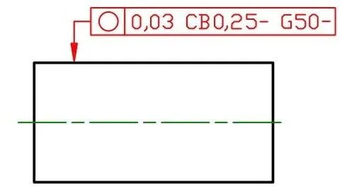
In contrast, the ISO GPS system prioritizes transparency and precision. There are no hidden defaults; every parameter must be explicitly stated to achieve the same measurement results as ASME. For instance, to match an ASME roundness tolerance measurement in ISO, the annotation would need to include:
- CB (Closing Ball Filter): Equivalent to the measurement machine’s spherical probe.
- 0.25: Specifies the probe tip radius as 0.25 mm.
- G (Gaussian Filter): Requires the use of a Gaussian filter.
- 50-: Indicates a nesting index of 50 UPR with a long-wave pass filter (retaining macro shapes while filtering out high-frequency noise).
The evaluation method defaults to an unconstrained minimum area (Chebyshev) fit, denoted by the symbol C, aligning with ASME’s approach.
Quick Reference Guide: ASME vs ISO Roundness Tolerance
To facilitate smooth transitions between ASME and ISO standards, we’ve compiled a handy reference table:
| ASME Annotation | ISO Equivalent Annotation |
|---|---|
| ⌀0.03 | ⌀0.03 CB0.25-G50- |
Tips for Avoiding Pitfalls:
- Explicitly State Parameters: When converting from ASME to ISO, always include CB and G filter parameters to prevent measurement discrepancies.
- Understand the “-” Symbol: In ISO annotations, the “-” after the numerical value indicates a long-wave pass filter, focusing on overall roundness rather than surface micro-roughness.
- Be Cautious with Other Geometric Tolerances: While ASME specifies default measurement conditions for roundness, it does not do so for flatness, straightness, or cylindricity. The differences between the two systems are even more pronounced for these tolerances.
Conclusion
Achieving equivalent roundness tolerance measurements across ASME and ISO standards requires a deep understanding of the underlying measurement principles and parameters. By grasping the concepts of CB simulated probes and G simulated filters, you can bridge the technical gap between these two systems, ensuring consistent and accurate quality control.